Free Service Hotline:
Free Service Hotline:

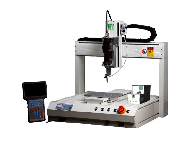
As automation equipment, automatic screw-driving machine should be debugged before putting into production. Let's take a brief look at the debugging steps of the automatic screw-driving machine.
The main steps in the commissioning of the automatic screw locking machine are:
1. Brush debugging: After loading the screws, turn on or off the power to adjust the brush near the track. Observe and adjust the height of the brush so that the screws on the track and the brush have a slight contact.
2. Adjust the screw through the board: observe and adjust the height of the screw through the board so that it is slightly higher than the nut 0.2-0.3mm.
3. Sensor Adjustment: when the screws are located in the middle of the transmitting and receiving ends of the sensor, the machine senses the screws, the distributor stops rotating, and the LED light is on; when the screws are not sensed, the distributing carousel continues to rotate, and the LED light is off. To observe and adjust the height of the sensor (sensor adjusting screw).
4. Track and dosing module adjustment (the most critical): keep a certain gap between the track and the dosing plate. If the track and discharging plate impact, there will be a discharging plate repeatedly positive and negative phenomenon; if the gap is too large, the screws may be stuck in the gap or fall into the machine; if the track and discharging plate contact, the friction increases, even if the vibration is adjusted to the larger, the screws are also transported ineffectively. Adjustment method: loosen the track fixing screws (at the track adjusting holes), push and pull the track to a suitable position. Fix the track and loosen the dividing module. Fixing screw, move the dividing module left and right, up and down, so that the dividing plate does not have contact with the track. At the same time, the surface of the dividing plate is level with or slightly lower than the surface of the track, and the exit of the track is facing the gap of the dividing plate, and finally fix the dividing module.
5. Adjustment of pressure panel height: Observe and adjust the height of the nut pressure panel, so that it is slightly higher than the nut 0.2-0.3MM. There should be no overlap among the nuts.
6. Vibration adjustment: the supply speed of the screw is related to the screw type and vibration. If the speed is not quite satisfactory, it can be adjusted. (If necessary, the back cover can be removed and adjusted). Adjustment method: loosen the vibration positioning screw (rear of the machine), rotate the vibration, adjusting screw (bottom of the machine). Clockwise to enhance, and vice versa to weaken. Observe and adjust to the appropriate feeding speed, the track must not collide with the material distribution plate, and the screw must not fall in the gap at the front of the track, referring to the section on adjusting the track. Finally tighten the vibration positioning screws.
7. Stop interval adjustment: When this machine senses screws between sensors, the dividing disk will stop rotating immediately, while the main motor will continue to select the feeding and stop running after a period of time. Adjusting the length of time can maintain the consistency of screw transportation. Rotate to adjust the stopping interval ( clockwise to lengthen, counterclockwise to shorten).